Hey everyone, new guy here.
I'm not sure if this is the right forum / section for this question, but this community seems to have some people who have already done what I'm trying to accomplish.
As a small part of a larger project, I'm trying to get my Arduino UNO board to act as a controller for my Sega Genesis. After looking over this pinout info, I was easily able to simulate button presses of UP and DOWN since these are dependent on single pins having either a high or low voltage.
What is giving me trouble is the multiplexed pins, specifically pin9 which controls both the START button and the C button. (here is a reddit post from someone who was having the exact same problem but never solved it).
Apparently the console sets the select pin (pin7) to either low or high, and the value of that pin determines whether pin9 should send the signal for the START button or the C button respectively.
In my Arduino sketch I'm using an interrupt and direct port manipulation rather than digital read and write in order to make things work as fast as possible (this is what people in the reddit thread suggested).
Despite these speed optimizations, the console is still registering that the START button and the C button are being pressed at the same time, rather than just the START button being pressed which is the behavior I'm trying to create.
My Arduino sketch simulates a button being pressed (ideally the START button) every 2 seconds. This button press consists of the button being held down for 1/4 of a second and then released.
I use an interrupt to detect when the select pin is changing voltage, and then immediately set a flag (selectIsLow) by reading the port register.
In my sendControllerSignals() function I check the selectIsLow flag, and if it is low I set pin9 to low, otherwise I set it to high.
This seems like it should be pressing only the START button, but it is pressing both START and C at the same time.
I'm thinking there is possibly some timing logic that needs to be implemented that I'm not aware of. I know multiple people here have built Sega Genesis / Mega Drive TASbots and have already solved this problem. If dwangoAC or MrYeah or whoever built this TASbot could provide some wisdom, I'd be grateful.
Here is the code for my Arduino sketch:
EDIT: removed whack code
Moderator, Senior Ambassador, Skilled player
(1142)
Joined: 9/14/2008
Posts: 1014
I spoke with GeoffLedak in IRC (Freenode #tasbot) and pointed out GhostSonic's initial Arduino design for Genesis. I don't have a MegaDrive myself and can't help a lot more from here but hopefully this is a good first step.
Also GeoffLedak, welcome to TASVideos!
This page might help as well.
It looks like changing the select pin pulls some other pins low from the multiplexer output. If you are only changing one pin (9) then it might be messing up the read routine in whatever game/rom you are testing with.
I was chatting with serisium in #tasbot and he informed me that it might be faster to poll the port registers in the main loop rather than using an interrupt.
Here is my updated sketch with the interrupt removed:
EDIT: removed broken code
This still has the same result of the Start and C buttons being pressed at the same time.
Interestingly, as a test I changed the code that reads pin7 to use a digitalRead function instead of polling the port register and that caused the Genesis to press only the C button and not the Start button, however it did not consistently press the button every 2 seconds like it is supposed to. It would skip a press or two every few iterations, and the expected behavior is that it should be pressing Start, not C. This leads me to believe that this is all definitely a timing issue and that the select pin is not being read fast enough.
After chatting with true in #tasbot I believe we've come up with a solution. I think it's the same technique that GhostSonic used for sending controller signals to the Genesis for his tasBot.
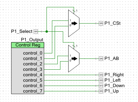
The Start button and the C button will both have their own dedicated digital pins on the arduino. These pins will be connected as inputs to a multiplexer which will output to pin9, and the select pin will be... the select signal for the multiplexer.
This should make pin9 always output the correct signal and we won't have to read the select signal in software at all.
It seems rather simple now that I remember how a multiplexer works. The computer organization course I took is slowly coming back to me... :)
Here's a screenshot of a PSoC schematic made by true
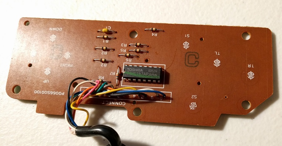
I just opened up a 3 button controller:
There's literally nothing inside it except for a few resistors, and the exact same 74HC157 multiplexer that GhostSonic used for his tasBot.
It's all making sense now...
Joined: 4/17/2010
Posts: 11591
Location: Lake Chargoggagoggmanchauggagoggchaubunagungamaugg
Please unembed that huge pic.
Warning: When making decisions, I try to collect as much data as possible before actually deciding. I try to abstract away and see the principles behind real world events and people's opinions. I try to generalize them and turn into something clear and reusable. I hate depending on unpredictable and having to make lottery guesses. Any problem can be solved by systems thinking and acting.
Thanks, that page was quite helpful when wiring up everything.
I thought I'd document the completed project in case anyone happens to come along this thread and wants to do something similar. It's quite basic but should provide a foundation for someone who doesn't know much about electronics like me.
Here is the final version of the Arduino sketch. All it does is press the start button every 2 seconds (a button press consists of holding down the button and then releasing it after 1/4 of a second):
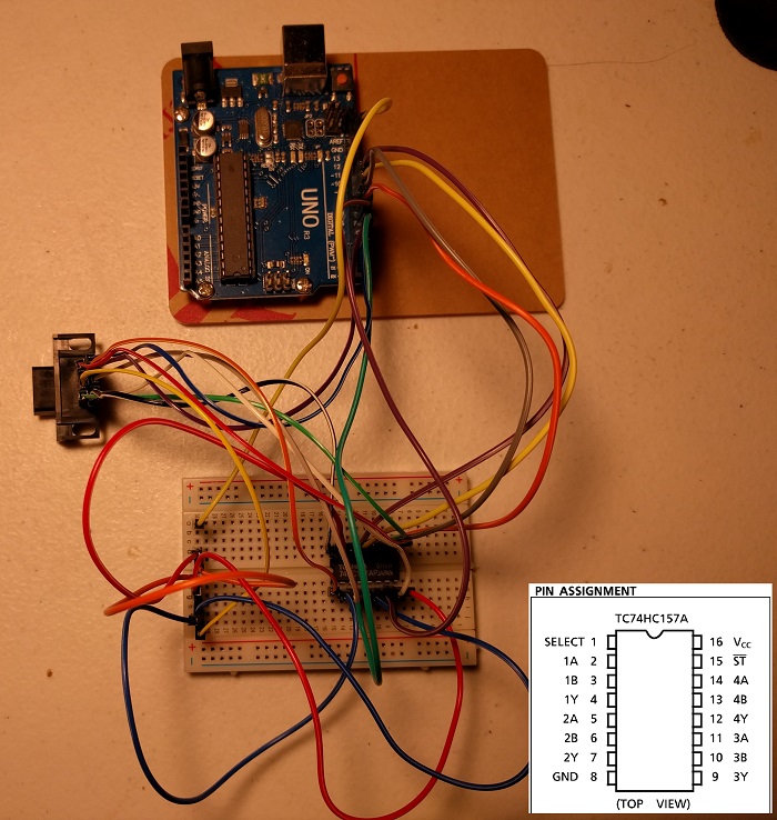
I picked up some 74HC157AP multiplexers on ebay and put one on a breadboard. The Technical Information section on this page has all the information needed for wiring everything up.
I'm using this DB9 connector. If you remove the screws and the metal shielding it fits perfectly into a genesis controller extension cable. The PCB mounting pins are also great for connecting female jumper wires.
.


 There's literally nothing inside it except for a few resistors, and the exact same 74HC157 multiplexer that GhostSonic used for his tasBot.
It's all making sense now...
There's literally nothing inside it except for a few resistors, and the exact same 74HC157 multiplexer that GhostSonic used for his tasBot.
It's all making sense now...

 .
.